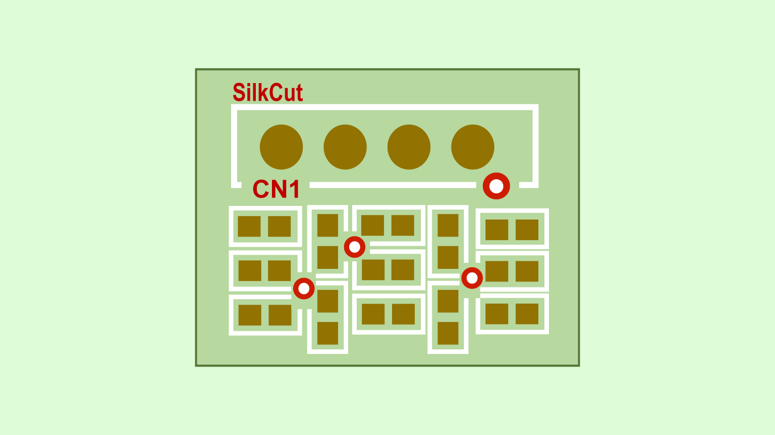
For high-density designs with many components, it could be hard to place references or vias in the areas where components are arranged densely. With the Subtract feature, you can easily cut out the section of component silkscreen that is overlapping the references / vias on the PCB sheet. This article explains how you can edit component silkscreen with the Subtract command.
目次
Cutting Out Component Silkscreen
Step
- Enable the Enable Component Editing option located at the bottom of the screen. This will allow you to edit the footprint models on the PCB sheet.
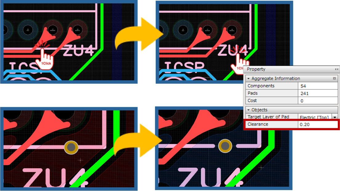
- Select the Subtract command from the context menu.
- Specify the value for the clearance required at the Property window. In the sample clip above the value is set to 0.2mm.
- Select a component silkscreen line.
- Select a reference or via.
=> The section of the component silkscreen line that is overlapping a reference / via will be removed.
Disable the Enable Component Edition option after finishing editing component silkscreen.
Reference Links